
Current Electricity Mcqs For NEET
NEET Physics For Current Electricity Multiple Choice Questions
Question 1. A steady current of 1.5 amp flows through a copper voltameter for 10 minutes. If the electrochemical equivalent of copper is 30 x 105 g coulomb-1, the mass of copper deposited on the electrode will be:
- 0.50 g
- 0.67 g
- 0.27 g
- 0.40 g.
Answer: 4. 0.40 g
Given that,
A steady current of 1.5 amp flows through a copper voltameter for 10 minutes. If the electrochemical equivalent of copper is 30 x 105 g coulomb-1,
I = 1.5A, t= 10 min = 600 sec
and z=30 \(\times 10^{-5} \mathrm{~g} \) coulomb \( ^{-1}\)
According to faraday first law of electrolysis, m=Z I T=30 \(\times 10^{-5} \times 1.5 \times 600=0.27 \mathrm{~g}\)
Question 2. Two have the same conductor length and are the same made resistance. up of the material them and has 1 volt a circular cross-section of the area \(A_1\) and the other one has a square cross-section of area \(A_2\). The ratio \(\frac{A_1}{A_2}\)is :
- 1.5
- 1
- 0.8
- 2
Answer: 2. 1
Given
Two have the same conductor length and are the same made resistance. up of the material them and has 1 volt a circular cross-section of the area \(A_1\) and the other one has a square cross-section of area \(A_2\).
From question, \(R_1=R_2\) and \(l_1=l_2\) Hence, Resistance, R=\(\rho \frac{l}{A}\)
⇒ \(\frac{R_1}{R_2}=\frac{l_1}{l_2} \cdot \frac{A_2}{A_1}\)
⇒ \(\frac{R_1}{R_2}=\frac{l_1}{l_2} \cdot \frac{A_2}{A_1}\)
∴ \({A_2}/{A_1}\)=1 .
Question 3. The resistance of a wire is R ohm. If it is melted and stretched to n times its original length, its new resistance will be:
- nR
- \(\frac{R}{n}\)
- \(n^2 R\)
- \(v\frac{R}{n^2}\)
Answer: 1. nR
In both cases the volume of material is the same, \(A_1 l_1=A_2 l_2\)
It is also given, \(l_2=n l_1\)
⇒ \(A_1 l_1=A_2 n l_1\)
⇒ \(A_2 =\frac{A_1}{n}\)
Now when the wire is stretched the resistance
⇒ \(R_1=\rho \frac{l_1}{A_2}=\rho \cdot \frac{n l_1}{\frac{A_1}{n}}\)
∴ \( R_1=R \boldsymbol{n}^2 [\text { Since } R=(\rho \frac{l_1}{A_2})]\)
Read and Learn More NEET Physics MCQs
Current Electricity Mcqs For NEET
Question 4. A wire of resistance 4 Ω is selected to twice its original length. The resistance of a stretched wire would be:
- 2 Ω
- 4 Ω
- 8 Ω
- 16 Ω
Answer: 4. 16 Ω
R=\(\frac{\rho l}{A}=4 \Omega\)
New length i’= 2i
on stretching volume remains constant
Resistance of stretched wire is,
⇒ \(\mathrm{R}^{\prime} =\frac{\rho l^{\prime}}{A^{\prime}}=f \frac{(2 l)}{(A / 2)}=\frac{4 \rho l}{A}\)
= 4 \(\times 4=16 \Omega\)
Question 5. A wire of a certain material is stretched slowly by ten percent. It’s new resistance and specific resistance become respectively:
- 1.2 times, 1.1 times
- 1.21 times, same
- both remain the same
- 1.1 time, 1.1 times
Answer: 2. 1.21 times, same
After stretching, specific resistance (\( \rho \)) will remain the same.
Original resistance of the wire
or \(\mathrm{R}=\rho \frac{l}{A}\)
or \(\mathrm{R} \propto \frac{l}{A}\)
and \(\mathrm{R} \propto \frac{l^2}{V} (as V=Al) \)
⇒ \(\frac{R^{\prime}}{R}=\frac{\left(l+\frac{10}{100} l\right)^2}{l^2}\)
⇒ \(\frac{R^{\prime}}{R} =\frac{\left(\frac{11}{10} l\right)^2}{l^2}=\frac{121}{100}\)
∴ \(R^{\prime}\) =1.21 R
Question 6. The electric resistance of a certain wire of iron is R. If its length and radius are both doubled, then:
- the resistance will be doubled and the specific resistance will be halved
- the resistance will be halved and the specific resistance will remain unchanged
- the resistance will be halved and the specific resistance will be doubled
- the resistance and the specific resistance, both will remain unchanged
Answer: 2. the resistance will be halved and the specific resistance will remain unchanged
Resistance of wire R=\(\rho \frac{l}{A}\)
Means R \(\propto \frac{l}{A}=\frac{l}{\pi r^2}\)
According to the question when l and R are doubled
⇒ \(R_1 \propto \frac{2 l}{\pi(2 r)^2}\)
⇒ \(R_1 \propto \frac{1}{2} R\)
Here specific resistance of the wire is independent of the geometry wire so it depends on the material of the wire.
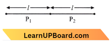
Question 7. A 6-volt battery is connected to the terminal of a three-metre-long wire of uniform thickness and resistance of 100 ohms. The difference of potential between two points on the wire separated by a distance of 50 cm will be:
- 2 volt
- 3 volt
- 1 volt
- 1.5 volt
Answer: 3. 1 volt
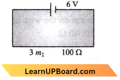
Voltage on 50 cm =\(\frac{6}{300} \times 50\)
=1 volt
Current Electricity Questions NEET
Question 8. There are three copper wires of length and cross-sectional area (2 L, A/2) (1/2, 2 A). In which case is the resistance minimum?
- It is the same in all three cases
- Wire of cross-sectional area 2 A
- Wire of cross-sectional area A
- Wire of cross-sectional area A
Answer: 2. Wire of cross-sectional area 2 A
The relation between the length and cross-section area of a wire is given by, \(\mathrm{R}=\frac{\rho I}{A}\) → Equation 1
where, \(\rho\) specific resistance. It is the proportionality constant and depends on the nature of the material.
(1) Length =\(\frac{L}{2}\),
cross-sectional area =2 \(\mathrm{~A}\)
Putting in Eq. (1), we get
∴ \(\mathrm{R}=\frac{\rho(\mathrm{L} / 2)}{2 A}=\frac{\rho L}{4 A}\)
(2)Length =L, cross-sectional area =A
Putting in (1), we get
∴ \(\mathrm{R}=\frac{\rho L}{A}\)
(3)Length =2 L, cross-sectional area =\(\frac{A}{2}\)
Putting in (1), we get
⇒ \(\mathrm{R}=\rho \frac{2 L}{A / 2}=\frac{4 \rho L}{A}\)
It is clear from above, that resistance is minimum only in option(B).
Question 9. If a negligibly small current is passed through a wire of length 15 m and of resistance \(5 \Omega\) having the uniform cross-section of \(6 \times 10^{-7} \mathrm{~m}^2\), then coefficient of resistivity of the material, is
- 1 \(\times 10^{-7} \Omega-\mathrm{m}\)
- 2 \(\times 10^{-7} \Omega-\mathrm{m}\)
- 3 \(\times 10^{-7} \Omega-\mathrm{m}\)
- 4 \(\times 10^{-7} \Omega-\mathrm{m}\)
Answer: 2. 2 \(\times 10^{-7} \Omega-\mathrm{m}\)
Given, l =15 \(\mathrm{~m}\)
A = 6 \(\times 10^{-7} \mathrm{~m}^2\)
R = 5 \(\Omega, \rho\)=?
We have, \(\rho =\frac{R A}{l} \)
= \(\frac{5 \times 6 \times 10^{-7}}{15} \)
= 2 \(\times 10^{-7} \Omega-\mathrm{m}\)
Question 10. A copper wire of length 10m and radius \(\left(\frac{10^{-2}}{\sqrt{\pi}}\right) m\) has an electrical resistance of \(10 \pi\). The current density in the wire for an electric field strength of 10 (v/m) is:
- \(104 \mathrm{~A} / \mathrm{m}^2\)
- 106 \(\mathrm{~A} / \mathrm{m}^2\)
- 10-5 \(\mathrm{~A} / \mathrm{m}^2\)
- 105 \(\mathrm{~A} / \mathrm{m}^2\)
Answer: 4. 105 \(\mathrm{~A} / \mathrm{m}^2\)
Given, R=10 \(\Omega, E=10 \mathrm{v} / \mathrm{m}, l=10 \mathrm{~m}\)
Radius, r=\(\frac{10^{-2}}{\sqrt{\pi}} m\)
We know, \(\rho =\frac{R A}{l}=\frac{10 \times \pi \times \frac{10^{-4}}{\sqrt{\pi}}}{10}\)
= \(10^{-4} \pi \mathrm{m}\)
Current density, J=E \(\sigma=\frac{E}{\rho}=\frac{10}{10^{-4}}=10^5 \mathrm{~A} / \mathrm{m}^2\)
Current Electricity Questions NEET
Question 11. Column 1 gives certain physical terms associated with the flow of current through a metallic conductor.
Column 2 gives some mathematical relations involving electrical quantities. Match Column-1 and Column-2 with appropriate relating
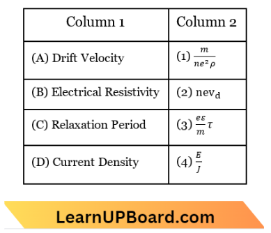
- (A)-(3), (B)-(4), (C)-(1), (D)-(5)
- (A)-(3), (B)-(4), (C)-(2), (D)-(4)
- (A)-(3), (B)-(1), (C)-(4), (D)-(2)
- (A)-(3), (B)-(2), (C)-(4), (D)-(1)
Answer: 1. (A)-(3), (B)-(4), (C)-(1), (D)-(5)
Drift velocity, \(\mathrm{v}_d=\frac{e E}{m} \tau\)
Current density, \(\mathrm{J}=\frac{I}{A}=\frac{n e A v_d}{A}=n e v_d\)
Resistivity, \(\rho=\frac{m}{n e^2 \tau}\)
⇒ \(\tau=\frac{m}{n e^2 \rho}\)
Resistance, \(\mathrm{R}=\mathrm{V} / \mathrm{I}\)
⇒ \(\rho \frac{l}{\mathrm{~A}}=\frac{\mathrm{E} l}{\mathrm{I}}\)
∴ \(\rho=\frac{\mathrm{E}}{\mathrm{I}}\)
Question 12. In a potentiometer circuit, a cell of EMF 1.5V gives a balance point at 36 cm length of wire. If another cell of EMF 2.5 V replaces the first cell, then at what length of the wire, the balance point occur?
- 60 cm
- 21.6 cm
- 64 cm
- 62 cm
Answer: 1. 60 cm
Given,\(\varepsilon_1=1.5 \mathrm{~V}\)
Balance length, \( l_1 =36 \mathrm{~cm}\)
⇒ \(\varepsilon_2 =2.5 \mathrm{~V}\)
⇒ \(l_2\) =?
We know, \(\varepsilon=\phi l\)
⇒ \(\frac{\varepsilon_1}{\varepsilon_2}=\frac{l_1}{l_2} \)
⇒ \(l_2=\frac{\varepsilon_2 l_1}{\varepsilon_1}=\frac{2.5 \times 36}{1.5}\)
∴ \(-l_2=36 \times \frac{5}{3}=60 \mathrm{~cm}\)
Question 13. Across a metallic conductor of a non-uniform cross-section, a constant potential difference is applied. The quantity which remains constant along the conductor is:
- current density
- current
- drift velocity
- electric field
Answer: 2. current
We know that, Current density, j=\(\frac{I}{A}\) → Equation 1
Drift velocity \(v_d=\frac{I}{n A_e}=\frac{j}{n e}\) → Equation 2
Electric field, E=\(\rho j\) → Equation 3
From eq. (1), (2) and (3) we confirm that current density, drift velocity, and electric field depend on the area of the conductor.
Even if the area of the cross-section of the conductor is nonuniform, the number of electrons flowing
Question 14. The resistance of a discharge tube is:
- zero
- ohmic
- non-ohmic
- infinity
Answer: 3. non-ohmic
In a discharge tube, the flow of positive ions and electrons causes the current. Moreover, secondary electron emission is possible. As a result of the nonlinearity of the V-I curve, its resistance will be nonohmic.
Question 15. From the graph between current I and voltage V shown in the figure, identify the portion corresponding to negative resistance.
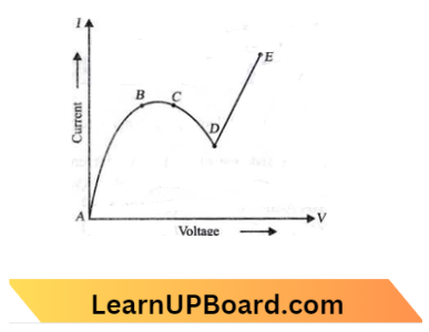
- DE
- BC
- CD
- AB
Answer: 2. BC
From Ohm’s law,R=\(\frac{\Delta V}{\Delta I}\)
If current decreases as voltage or temperature rises, then resistance is said to be negative.
In the V-I graph, The current drops with rising voltage in graph segment CD.
Thus, The negative resistance is represented by portion CD.
Question 16. The color code of resistance is given below: The values of resistance and tolerance respectively, are:

- \(47 \mathrm{k} \Omega, 10 \%\)
- 4.7 \(\mathrm{k} \Omega, 5 \%\)
- 470 \(\mathrm{k} \Omega, 5 \%\)
- 470 \(\mathrm{k} \Omega, 10 \%\)
Answer: 3. 470 \(\mathrm{k} \Omega, 5 \%\)
From the color code of carbon resistors
Code of yellow = 4
Code of violet = 7
Code of brown =\(10^1(multiples)\)
Code of gold = \(\pm 5 \% (tolerance)\)
Hence resistance of resistor =47 \(\times 10^1 \Omega \pm 5 \%\)
=470 \(\Omega \pm 5 \%\)
NEET Current Electricity Mcqs
Question 17. A carbon resistor of (47 ± 4.7) k\(\Omega\). is to be marked with rings of different colors for its identification. The color code sequence will be:
- Yellow – Green – Violet – Gold
- Yellow – Violet – Orange – Silver
- Violet – Yellow – Orange – Silver
- – Green – Orange – Violet – Gold
Answer: 2. Yellow – Violet – Orange – Silver
Seeing the table we confirm the color assigned to a number
4 → Yellow
7 → Violet
3 → Orange
and 10% accuracy says about the color of silver.
Hence the color code sequence will be yellow, violet, orange, and silver.
Question 18. As the temperature increases, the electrical resistance:
- increase for both conductors and semiconductors.
- decrease for both conductors and semiconductors.
- increase for conductors but a decrease for semiconductors
- decrease for conductors but increase for semiconductors
Answer: 3. increase for conductors but a decrease for semiconductors
Increase for conductors but decrease for semiconductors.
As the temperature increases, the resistance of the conductor increases, and for semiconductors decreases, because the temperature coefficient of resistance \((\propto)\) is positive for conductors and negative for insulators.
Question 19. The solids which have the negative temperature coefficient of resistance are:
- insulator only
- semiconductor only
- insulators and semiconductors
- metals
Answer: 3. insulators and semiconductors
The negative temperature coefficient of the resistance is only present in the insulators or the semiconductors. In, these, the resistance decreases with an increase in temperature.
Question 20. Which of the following graphs represents the variation of resistivity (p) with temperature (7) for copper?
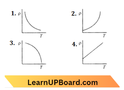
Answer: 2.
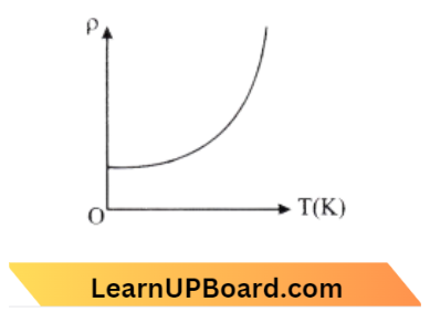
For copper at 0 \(\mathrm{~K} \), the value of resistivity is 1.7 \(\times 10^{-8} \Omega \mathrm{m}\).
Current Electricity Mcqs With Answers
Question 21. The specific resistance of a conductor increases with the:
- increase in the temperature
- increase in the cross-section area
- increase in the cross-section and decrease in the length
- increase in the cross-section area
Answer: 1. increase in the temperature
The specific resistance of conduction increases with increases in the temperature.
Question 22. Two resistors of resistance, 100 Ω, and 200Ω, are connected in parallel in an electrical circuit. The ratio of the thermal energy developed in 100 Ω to that in 200Ω in a given time is:
- 1: 2
- 2: 1
- 1: 4
- 4: 1
Answer: 2. 2: 1
We know, \(\mathrm{H}=\frac{V^2}{R} t\)
so,\(\mathrm{H}_1=\frac{V^2}{100} t\)
⇒ \(\mathrm{H}_2=\frac{V^2}{200} t\)
so,\(\frac{\mathrm{H}_1}{\mathrm{H}_2}=\frac{200}{100}\)=2: 1
Question 23. Which of the following acts as a circuit protection device?
- Inductor
- Switch
- Fuse
- Conductor
Answer: 3. Fuse
Equipment, machinery components, and devices in electrical and electronic circuits against short circuits, over-currents, and earth faults are called protective devices.
Protective devices are necessary to protect electrical appliances or equipment.
From the given devices fuse is used in electric circuits as a protective device, it helps prevent excessive amounts of current from flowing in the circuit or from short-circuiting.
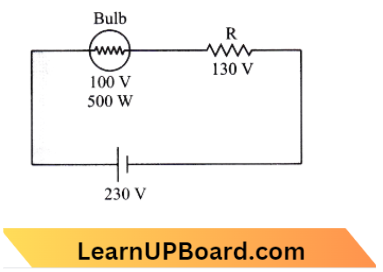
Question 24. A filament bulb (500 W, 100 V) is to be used in a 230 V main supply. When a resistance R is connected in series, it works perfectly and the bulb consumes 500 W. The value of R is:
- 230 Ω
- 46 Ω
- 26 Ω
- 13 Ω.
Answer: 3. 26 Ω
Current through bulb, \(\mathrm{I}=\frac{P}{V}=\frac{500 \mathrm{~W}}{100 \mathrm{~V}}\)
R =\(\frac{130 \mathrm{~V}}{5 \mathrm{~V}}=26 \Omega\)
Current Electricity Mcqs With Answers
Question 25. The two cities are 150 km apart. Electric power is sent from one city to another city through copper wires. The fall of potential per km is 8 V and the average resistance per km is 0.5 Q. The power loss in the wire is:
- 19.2 W
- 19.2 kW
- 19.2 J
- 12.2 kW
Answer: 2. 19.2 kW
Given the potential difference between the two cities
V =8 \(\times 150=1200 \mathrm{~V}\)
Average resistance =0.5 \(\times 150=75 \Omega\)
Power loss, \(\mathrm{P} =\frac{V^2}{R}=\frac{1200 \times 1200}{75}\)
=19200 W
=192 kW
Question 26. If the voltage across a bulb rated 220 V, 100 W drops by 2.5% to its rated value the percentage at the rated value by which the power would decrease is its:
- 20%
- 2.5%
- 5%
- 10%
Answer: 3. 5%
We know power, \(\mathrm{P}=\frac{V^2}{R}\)
⇒ \(\frac{\Delta P}{P} \times 100 \% =\frac{2 \Delta P}{V} \times 100 \%\)
=2.25=5 %
Question 27. In producing chlorine by electrolysis 100 kW power at 125 V is being consumed. How much chlorine per minute is liberated (ECE of chlorine is 0.367 x 10⁻⁶ kgC-1).
- 1.76 x 10⁻³ kg
- 9.67 x 10⁻³ kg
- 17.61 x 10⁻³ kg
- 3.67 x 10⁻³ kg
Answer: 1. 1.76 x 10⁻³ kg
According to the question, Mass of the substance deposited at the cathode, m = ZIt
= Z\(\left(\frac{P}{V}\right)\) t
= 0.367 \(\times 10^{-6} \times \frac{100 \times 10^3}{125} \times 60\)
= 17.6 \(\times 10^{-3} \mathrm{~kg}\)
Question 28. A cell can be balanced against 110 cm and 100 cm of potentiometer wire, respectively with and without being short-circuited through a resistance of 10 Ω. Its internal resistance is:
- 1.0Ω
- 0.5Ω
- 2.0 Ω
- zero
Answer: 1. 1.0 Ω
In a potentiometer experiment, when we find the internal resistance of a cell. Let E be the emf of the cell and V the potential difference. Then
⇒ \(\frac{E}{V}=\frac{l_1}{l_2}[l_1 and l_2 \) are length of wire ]Since \(\frac{E}{V}=\frac{R+r}{R}[E=I(R+r) an V=\mathrm{I} R]\)
⇒ \(\frac{R+r}{R} =\frac{l_1}{l_2}\)
⇒ \(1+\frac{r}{R} =\frac{110}{100} \)
⇒ \(\frac{r}{R} =\frac{10}{100}\)
r=\(\frac{1}{10} \times 10=1 \Omega\)
NEET Physics Important Questions
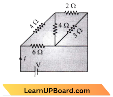
Question 29. The total power dissipated in watts in the circuit shown here is:

- 40
- 54
- 4
- 16
Answer: 2. 54
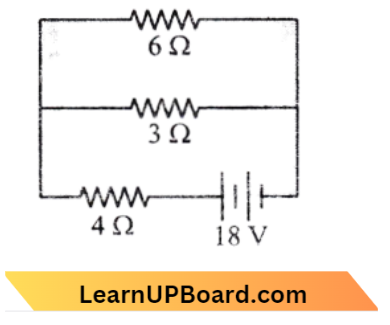
Total power dissipated, \(\mathrm{P}=\frac{V^2}{R}\)
= \(\frac{18 \times 18}{6}=54 \mathrm{~W}\)
Question 30. In producing chlorine through electrolysis 100 watt power at 125 V is being consumed. How much chlorine per minute is liberated? E. C. E. of chlorine is 0.367 x 10⁻⁶kg/coulomb:
- 13.6 mg
- 17.6 mg
- 21.3 mg
- 24.3 mg
Answer: 2. 17.6 mg
P=100 \(\mathrm{~W}, V=125 \mathrm{~V}\)
P=V I
-I=\(\frac{P}{V}=\frac{100}{125} \mathrm{~A}\)
Mass of chlorine liberated =2 \(\mathrm{It}\)
= 0.367 \(\times 10^{-6} \times \frac{100}{125} \times 60 \)
= 0.0176 \(\times 10^{-3} \mathrm{~kg}\)
=17.6 \(\mathrm{mg}\)
Question 31. A 5-ampere fuse wire can withstand a maximum power of 1 watt in the circuit. The resistance of the fuse wire is:
- 0.04 ohm
- 0.2 ohm
- 5 ohm
- 0.4 ohm
Answer: 1. 0.04 ohm
P =\(I^2 R \)
I =\(25 \times R\)
R =\(\frac{1}{25}=0.04 \Omega\)
NEET Physics Important Questions
Question 32. When three identical bulbs of 60-watt, 200-volt rating are connected in series to a 200-volt supply, the power drawn by them will be:
- 60 watt
- 180 watt
- 10 watt
- 20 watt
Answer: 4. 20 watt
The resistance of each bulb is \(\frac{V^2}{P}=\frac{(200)^2}{60} \Omega\) when three bulbs are connected in series then equivalent resistance is, \(\frac{3 \times(200)^2}{60}\).
Power,P=\(\frac{V^2}{R_{e q}}=20 \mathrm{~W}\).
Question 33. In India electricity is supplied for domestic use at 220 V. It is supplied at 110 V in the USA. If the resistance of a 60 W bulb for use in India is R, the resistance of a 60 W bulb for use in the USA will be:
- \(\mathrm{R}\)
- 2 \(\mathrm{R}\)
- \(\frac{R}{4}\)
- \(\frac{R}{2}\)
Answer: 3. \(\frac{R}{4}\)
In India, \(P_1=\frac{(220)^2}{R}\)
In USA \(P_V=\frac{(110)^2}{R_0}\)
As \(P_1=P_V\)
⇒ \(\frac{(220)^2}{R}=\frac{(110)^2}{R_V}\)
⇒ \(R_v=\frac{110 \times 110}{220 \times 220}\)
∴ \(R_v=\frac{R}{4}\)
Question 34. A fuse wire is a wire of:
- high resistance and high melting point
- high resistance and low melting point
- low resistance and low melting point
- low resistance and high melting point
Answer: 2. high resistance and low melting point
Fuse wire must have high resistance (per unit length) and low melting point.
Question 35. Two bulbs 25 W, 22 V, and 100 W, 220 V are given. Which has higher resistance?
- 25 W bulb
- 100 W bulb
- Both bulbs have equal resistance
- The resistance of bulbs cannot be compared
Answer: 1. 25 W bulb
We have, power of electric bulb, P=\(\frac{V^2}{R}\)
R=\(\frac{V^2}{P}\)
For the same potential difference V,
R \(\propto \frac{1}{P}\)
As a result, we can see that when power is low, resistance is high, and vice versa.
Given,\(P_1=25 \mathrm{~W}, P_2=100 \mathrm{~W}\),
⇒ \(V_1=V_2=220 \mathrm{~V}\)
∴ Hence, the resistance of 25 \(\mathrm{~W}\) bulb is maximum and 100 \mathrm{W} bulb is minimum.
NEET Important Questions Current Electricity
Question 36. A current of 2 A, passing through a conductor produces 80 J of heat in 10 s. The resistance of the conductor in the ohm is:
- 0.5
- 2
- 4
- 20
Answer: 2. c
The work done in carrying a charge q from one end to the other end of a conductor with the potential difference V equals the amount of heat created in that conductor.
⇒ \(H=W=V q=V i t=i^2 R t\) [Since, V=I R ]
H=\(i^2 R t J \)
R=\(\frac{H}{\left(i^2 t\right)}\)
Given, H=80 \(\mathrm{~J}, i=2 \mathrm{~A}, t=10 \mathrm{~s}\),
So,R=\(\frac{80}{(2)^2 \times 10}=2 \Omega\)
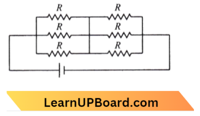
Question 37. The effective resistance of a parallel connection that consists of four wires of equal length, equal area of cross-section, and the same material is 0.25 \(\Omega\). What will be the effective resistance if they are connected in series?
- \(0.25 \Omega\)
- 0.5 \(\Omega \)
- 1 \(\Omega \)
- 4 \(\Omega\)
Answer: 4. 4 \(\Omega\)
Given, Parallel connection,
No. of wires =4
Length =l
Area = A is the same
Material =f is the same
⇒ \(\mathrm{R}_{\text {eff }} =0.25 \Omega\)
⇒ \(\mathrm{R}_{\mathrm{S}}\) =?
⇒ \(\mathrm{R}_{\mathrm{P}} =\frac{\mathrm{R}}{n}=\frac{\mathrm{R}}{4}\)
= 0.25
⇒ \(\mathrm{R}=1 \Omega\)
∴ \(\mathrm{R}_{\mathrm{S}}=n \mathrm{R}=4 \mathrm{R}=4 \Omega\)
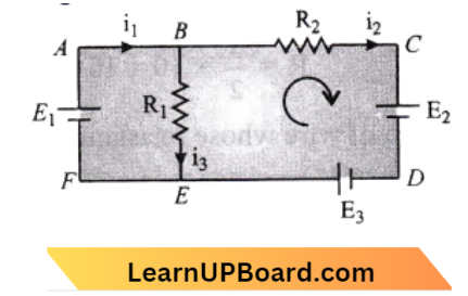
Question 38. Three resistors having resistances \(r_1, r_2, r_3\) are connected as shown in the given circuit. The ratio \(\frac{i_3}{i_1}\) of currents in terms of resistances used in the circuit is:
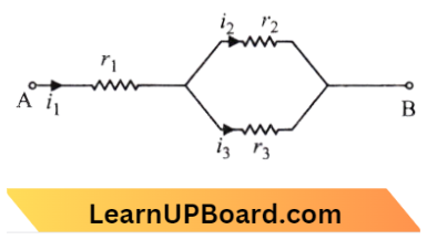
- \(\frac{r_1}{r_2+r_3}\)
- \(\frac{r_2}{r_2+r_3}\)
- \(\frac{r_1}{r_1+r_2}\)
- \(\frac{r_2}{r_1+r_3}\)
Answer: 2. \(\frac{r_2}{r_2+r_3}\)
Given, \(\frac{l_3}{i_1}\)= ?
we know,\( i_1=i_2+i_3\)
and \(i_2 r_2 =i_3 r_3 \)
⇒ \(i_2 =i_1-i_3\)
⇒ \(\left(i_1-i_3\right) r_2 =i_3 r_3 \)
⇒ \(i_1 r_2 =i_3\left(r_2+r_3\right) \)
∴ \(\frac{i_3}{i_1} =\frac{r_2}{r_2+r_3}\)
NEET Important Questions Current Electricity
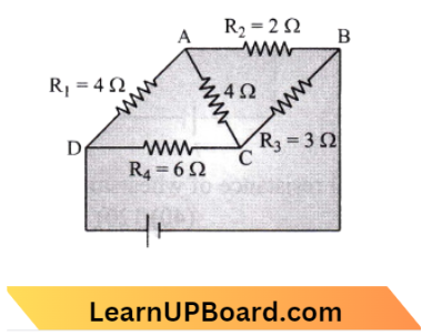
Question 39. The equivalent resistance between A and B for the mesh shown in the figure is:
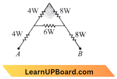
- 72 W
- 16 W
- 30 W
- 4.8 W
Answer: 2. 16 W
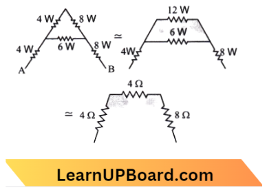
Now 4 \(\Omega, 4 \Omega and 8 \Omega\) are in series.
So, \(R_5=4 \Omega+4 \Omega+8 \Omega=16 \Omega\)
Question 40. In the circuit shown below, the reading of voltmeters and the ammeters will be:
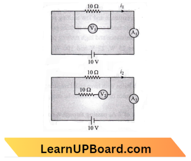
- \(V_1=V_2\) and \(i_1>i_2\)
- \(\mathrm{V}_1=\mathrm{V}_2\) and \(\mathrm{i}_1=\mathrm{i}_2\)
- \(\mathrm{V}_2=\mathrm{V}_1\) and \(\mathrm{i}_1>\mathrm{i}_2\)
- \(\mathrm{V}_1=\mathrm{V}_2\) and \(\mathrm{i}_1=\mathrm{i}_2\)
Answer: 2. \(\mathrm{V}_1=\mathrm{V}_2\) and \(\mathrm{i}_1=\mathrm{i}_2\)
For an ideal voltmeter, resistance is infinite and for the ideal ammeter, resistance is zero.
⇒ \(V_1=i_1 \times 10=\frac{10}{10} \times 10=10 \text { volt }\)
⇒ \(V_2=i_2 \times 10=\frac{10}{10} \times 10=10 \text { volt }\)
⇒ \(V_1=V_2\)
∴ \(i_1=i_2=\frac{10 \mathrm{~V}}{10 \Omega}=1 \mathrm{~A}\)
Physics Mcqs For NEET Current Electricity
Question 41. The reading of an ideal voltmeter in the circuit shown is
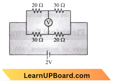
- 0.6 V
- 0 V
- 0.5 V
- 0.4 V
Answer: 4. 0.4 V
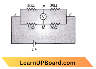
Current in A P B=\(\frac{2}{50} \mathrm{~A}\)
Current in A Q B=\(\frac{2}{50} \mathrm{~A}\)
⇒ \(\Delta \mathrm{V}\) from A to P,
⇒ \(V_{\mathrm{A}}=\frac{2}{50} \times 200=V_{\mathrm{P}}\)
⇒ \(\Delta\) V from A to Q,
⇒ \(V_{\mathrm{A}} =\frac{2}{50} \times 30=V_{\mathrm{Q}}\)
⇒ \(V_{\mathrm{P}}+\frac{2}{50} \times 20 =V_{\mathrm{Q}}+\frac{2}{50} \times 30\)
∴ \(V_{\mathrm{P}}-V_{\mathrm{Q}} =0.4 \mathrm{~V}\)
Question 42. A, B, and C are voltmeters of resistance R, 1.5 R, and 3 R respectively as shown in the figure. When some potential difference is applied between X and Y, the voltmeter readings are \(V_A, V_B, and V_C \) respectively.
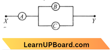
- \(V_A=V_B=V_C\)
- \(V_A \neq V_B+V_C\)
- \(\mathrm{V}_{\mathrm{A}}=\mathrm{V}_{\mathrm{B}} \neq \mathrm{V}_{\mathrm{C}}\)
- \(\mathrm{V}_{\mathrm{A}} \neq \mathrm{V}_{\mathrm{B}} \neq \mathrm{V}_{\mathrm{C}}\)
Answer: 1. \(V_A=V_B=V_C\)
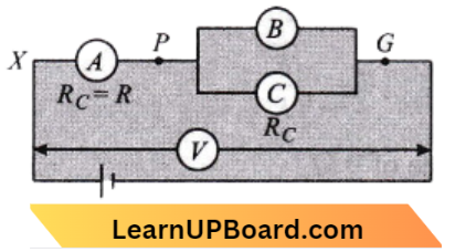
As in the figure, resistance \(R_B\) and \(R_C\) of the voltmeter are in parallel. So their equivalent resistance \(R^{\prime} \) is,
⇒ \(\frac{1}{R^{\prime}} =\frac{1}{R_B}+\frac{1}{R_C}\)
⇒ \(\frac{1}{R^{\prime}} =\frac{1}{1.5 R}+\frac{1}{3 R} \)
⇒ \(\frac{1}{R^{\prime}} =\frac{2+1}{3 R}\)
⇒ \(R^{\prime}\) =R
So the voltage across \(X P is V_{X P}\),
= \(V_A=I R\)
Voltage across P Q is \(V_{P Q}\),
= \(V_B=V_C=I R \)
∴ \(V_A =V_B=V_C\)
Physics Mcqs For NEET Current Electricity
Question 43. Two metal wires of identical dimensions are connected in series. If \(\sigma_1\) and \(\sigma_2\) are the conductivities of the metal wires respectively, the effective conductivity of the combination is:
- \(\frac{2 \sigma_1 \sigma_2}{\sigma_1+\sigma_2}\)
- \(\frac{\sigma_1+\sigma_2}{2 \sigma_1 \sigma_2}\)
- \(\frac{\sigma_1+\sigma_2}{\sigma_1 \sigma_2}\)
- \(\frac{\sigma_1 \sigma_2}{\sigma_1+\sigma_2}\)
Answer: 1. \(\frac{2 \sigma_1 \sigma_2}{\sigma_1+\sigma_2}\)
From question, \(\rho =\text { resistivity }\)
A =\(\text { Area of cross-section }\)
⇒ \(R_1 =\rho_1 \frac{l}{A} \)
⇒ \(R_2 =\rho_2 \frac{l}{A}\)
and \(R_2=\rho_2 \frac{l}{A}\)
Net effective resistance, \(R_{e q} =R_1+R_2 \)
⇒ \(\rho \frac{2 l}{A} =\rho_1 \frac{l}{A}+\rho_2 \frac{l}{A}\)
∴ \(2 \rho =\rho_1+\rho_2\)
Now conductivity =\(\frac{1}{\text { resistivity }}=\frac{1}{\rho}\)
⇒ \(\frac{2}{\sigma} =\frac{1}{\sigma_1}+\frac{1}{\sigma_2}\)
⇒ \(\frac{2}{\sigma} =\frac{\sigma_1+\sigma_2}{\sigma_1 \sigma_2} \)
⇒ \(\sigma =\frac{2 \sigma_1 \sigma_2}{\sigma_1+\sigma_2}\)
The net effective conductivity of combined wire is,
∴ \(\sigma=\frac{2 \sigma_1 \sigma_2}{\sigma_1+\sigma_2}\)
Question 44. A circuit contains an ammeter, a battery of 30 V, and a resistance of 40.8 Ω all connected in series. If the ammeter has a coil of resistance 480 Ω and a shunt of 20 Ω, then the reading in the ammeter will be:
- 0.5 A
- 0.25 A
- 2 A
- 1A
Answer: 1. 0.5 A
The situation is shown in the diagram. Now effective resistance of the circuit is,
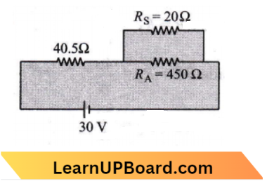
⇒ \(R_{e f f}=40.8+\frac{480 \times 20}{480+20}\)
Current, I=\(\frac{V}{R}=\frac{30}{60}=\frac{1}{2}=0.5 \mathrm{~A}\)
Reading of ampere =0.5 \(\mathrm{~A}\)
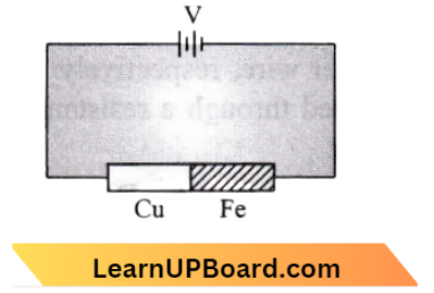
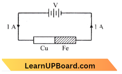
Question 45. Two rods are joined to the end, as shown. Both have a cross-sectional area of 0.01 cm2. Each is 1 meter long. One rod is of copper with a resistivity of 17 x 10-6 ohm- centimeter, the other is of iron with a resistivity of 105 ohm centimeter. How much voltage is required to produce a current of 1 ampere in the rods?
- 0.00145 V
- 0.0145 V
- 1.7 x 10⁻⁶ V
- 0.117 V
Answer: 4. 0.117 V
According to the question, the length of each rod, l = 1 m
Area of cross-section of each rod , \(\mathrm{A}=0.01 \mathrm{~cm}^2=0.01 \times 10^{-4} \mathrm{~m}^2\)
If \(\rho_{c u}\)= resistivity of copper and \(\rho_{c u}\) is resistivity of iron then,
⇒ \(\rho_{c u}=1.7 \times 10^{-6} \Omega \mathrm{cm}=1.7 \times 10^{-8} \Omega \)
⇒ \(\rho_{f e}=10^{-5} \Omega \mathrm{cm}=10^{-7} \Omega\)
New Resistance of \(\mathrm{Cu}\) rod,
⇒ \(\mathrm{R}_{c u}=\rho_{c u} \frac{l}{A}\)
and Resistance of iron rod, \(\rho_{f e}=\rho_{f e} \frac{l}{A}\)
Both are connected in series the equivalent resistance is,
⇒ \(R_{e s} =R_{c e}+R_{F e}\)
= \(\rho_{c u} \frac{l}{\mathrm{~A}}+\rho_{f e} \frac{l}{\mathrm{~A}}=\frac{l}{\mathrm{~A}} t(\rho_{c u}+\rho_{f e}) \)
V = I R { where } I=1 \(\mathrm{~A}\} \)
= I \(\left(R_{c u}+R_{f e}\right)\)
= \(1\left(\rho_{c u}+\rho_{f e}\right) l \)
= \(\left(\rho_{c u}+\rho_{f e}\right)\left(\frac{l}{\mathrm{~A}}\right) \)
= \(\left(1.7 \times 10^8+10^{-7}\right) \times\left(\frac{1}{0.01 \times 10^{-4}}\right)\)
= \(10^{-7}(0.17+1)\left(10^6\right) \)
= 1.17 \(\times 10^{-1} \mathrm{~V} \)
= 0.117 \(\mathrm{~V}\)
Current Electricity Practice Questions NEET
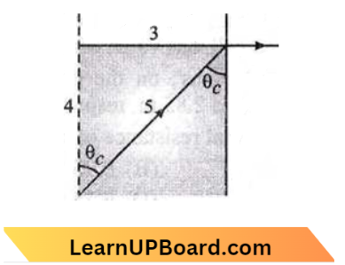
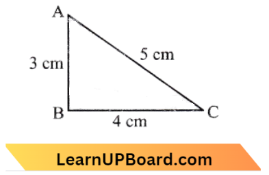
Question 46. A 12 cm wire is given the shape of a right-angled triangle ABC having sides 3 cm, 4 cm, and 5 cm as shown in the figure. The resistance between two ends (AB, BC, CA) of the respective sides is measured one by one by a multi¬meter. The resistance will be in the ratio:
- 9 : 16: 25
- 27 :32: 35
- 21 : 24: 25
- 3 : 4: 5
Answer: 2. 27:32: 35

Resistance of side A B=\(R_1=\frac{3 \rho}{\mathrm{A}}\)
Resistance of side B C=\(R_2=\frac{4 \rho}{\mathrm{A}}\)
Resistance of side A C=\(R_3=\frac{5 \rho}{\mathrm{A}}\)
(Where A= Area of cross-section and \(\rho\)= resistivity of wire)
The resistance between A and B is, \(\mathrm{R}_{\mathrm{AB}} =\frac{R_1\left(R_2+R_3\right)}{R_1+R_2+R_3}\)
= \(\frac{\frac{3 \rho}{A}\left(\frac{4 \rho}{A}+\frac{5 \rho}{A}\right)}{\frac{3 \rho}{A}+\frac{4 \rho}{A}+\frac{5 \rho}{A}}=\frac{27 \rho}{12 A}\)
Similarly \(R_{B C}=\frac{R_2\left(R_1+R_3\right)}{R_1+R_2+R_3}\)
= \(\frac{\frac{4 \rho}{A}\left(\frac{3 \rho}{A}+\frac{5 \rho}{A}\right)}{\frac{3 \rho}{A}+\frac{4 \rho}{A}+\frac{5 \rho}{A}}=\frac{32}{12} \frac{\rho}{A}\)
And \(R_{A C}=\frac{R_3\left(R_1+R_2\right)}{R_1+R_2+R_3}\)
= \(\frac{\frac{5 \rho}{A}\left(\frac{3 \rho}{A}+\frac{3 \rho}{A}\right)}{\frac{5 \rho}{A}+\frac{3 \rho}{A}+\frac{4 \rho}{A}}=\frac{35}{12} \frac{\rho}{A}\)
⇒ \(R_{A B}: R_{B C}: R_{A C} =\frac{27}{12}: \frac{32}{12}: \frac{35}{12}\)
=27: 32: 35
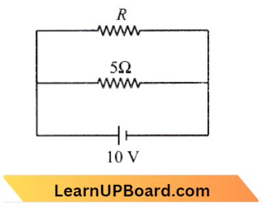
Question 47. The power dissipated in the circuit shown in the figure is 30 watts. The value of R is
- 20 Ω.
- 15 Ω
- 10 Ω.
- 30 Ω
Answer: 3. 10 Ω.
According to the question, R_1=R
⇒ \(R_2=5 \Omega, V=10 \mathrm{~V}, P=30 \mathrm{~W}\)
P=\(\frac{V_2}{R_1}+\frac{V_2}{R_2} \)
⇒ \(\frac{10^2}{\mathrm{R}}=30-\frac{10^2}{5}\)
⇒ \(\frac{100}{R}\)=30-20
∴ \(\mathrm{R}=10 \Omega\)
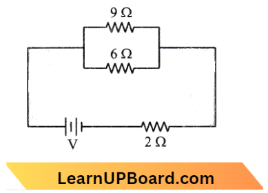
Question 48. If power dissipated in the 9Ω resistor in the circuit shown is 36 W, the potential difference across the 2 Ω resistor is:
- 8 V
- 10 V
- 2 V
- 4 V
Answer: 2. 10 V
We know that power, P=\(I^2 R\)
I=\(\sqrt{\frac{P}{R}}\)
for resistance of 9 \(\Omega\),
⇒ \(I_1 =\sqrt{\frac{36}{9}} \)
= \(\sqrt{4}=2 \mathrm{~A}\)
⇒ \(I_2 =\frac{I_1 \times R}{6}=\frac{2 \times 9}{6}=3 \mathrm{~A}\)
⇒ \(I_1 =I_1+I_2=2 \mathrm{~A}+3 \mathrm{~A}=5 \mathrm{~A}\)
∴ \(V_2 =I R_2=5 \times 2=10 \mathrm{~V}\)
Current Electricity Practice Questions NEET
Question 49. A current of 3 A flows through the 2Ω resistor shown in the circuit. The power dissipated in the 5 Ω is:
- 4 W
- 2W
- 1W
- 5W
Answer: 4. 5W
Voltage across all three branches are same.
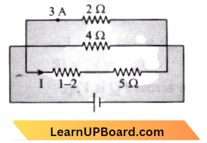
Voltage across 2 \(\Omega\) resistance,
V=2 \(\times 3=6 \mathrm{~V}\)
So voltage across lowest arm, \(V_1=6 \mathrm{~V}\) Current across\(5 \Omega\) is,
I=\(\frac{6}{1+5}=1 \mathrm{~A}\)
Power across 5 \(\Omega\) is,
P=\(I^2 R=(1)^2 \times 5=5 \mathrm{~W}\)
Question 50. In the circuit shown, the current through the 4 Ω resistor is 1 A when the point P and M are connected to a DC voltage source. The potential difference the points M and A is:
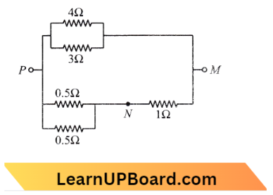
- 1.5V
- 1.0 V
- 1.0V
- 3.2 V
Answer: 4. 3.2 V
⇒ \(i_1=1 \mathrm{amp}\)= current through 4 \(\Omega\)
⇒ \(i_2\)=current through 3 \(\Omega\)
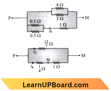
⇒ \(\frac{i_2}{i_2}=\frac{3}{4}\)
⇒ \(i_2=\frac{4}{3} \)
⇒ \(i_3=i_1+i_2=1+\frac{4}{3}=\frac{7}{3} \text { amp }\)
and \( \frac{i_3}{i_4}=\frac{3 / 4}{12 / 7} \)
⇒ \(\frac{7}{3} \times \frac{12}{7}=i_4 \times \frac{5}{4}\)
⇒ \(i_4 =\frac{16}{5}=3.2 \mathrm{amp}\)
⇒ \(\mathrm{V}_{\mathrm{NM}} \)={ P.D. across } M and N
= \(i_4 \times 1 \mathrm{~W}\)
= \(3.2 \times 1=3.2 \mathrm{Volt}\)
Current Electricity Practice Questions NEET
Question 51. Power dissipated across the 8 Ω, resistor in the circuit shown here is 2 watt. The power dissipated in watt units across the 3 Ω resistor is:

- 3.0 W
- 2.0 W
- 1.0W
- 0.5 W
Answer: 1. 3.0 W
1 \(\Omega\) and 3 \(\Omega\) are in, series so,
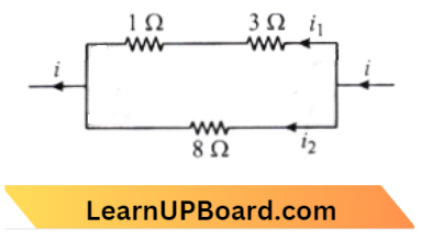
⇒ \(R_s=R_1+R_2\)
⇒ \(R_s=3+1=4 \Omega\)
and \(R_2=8 \Omega\)
i= current in the circuit
Current through \(R_1\) is,
⇒ \(i_1=\frac{i \times R_2}{R_1+R_2}=\frac{i \times 8}{12}=\frac{21}{3}\)
Current through \(R_2\) is,
⇒ \(i_2=\frac{1 \times R_1}{R_1+R_2}=\frac{i \times 4}{12}=\frac{i \times 8}{12}\)
Power dissipated in 3 \(\Omega\) resistance is,
⇒ \(P_1=i_1^2 \times 3\) → Equation 1
Power dissipated in 8 \(\Omega\) resistance is:
\(P_2=i_2{ }^2 \times 8\) → Equation 2
For (1) and (2)
⇒ \(\frac{P_1}{P_2}=\frac{i_1^2 \times 3}{i_2^2 \times 8} \)
⇒ \(\frac{P_1}{P_2}=\frac{\left(\frac{2 i}{3}\right)^2 \times 3}{\left(\frac{i}{3}\right)^2 \times 8}=\frac{3}{2}\)
∴ \(P_1=\frac{3}{2} \times P_2=\frac{3}{2} \times 2=3 \mathrm{~W}\)
Question 52. When a wire of uniform cross-section a, length l, and resistance R is into a complete circle, the resistance between any two diametrically opposite points will be:
- \(\frac{R}{4}\)
- 4 \(\mathrm{R}\)
- \(\frac{R}{8}\)
- \(\frac{R}{2}\)
Answer: 1. \(\frac{R}{4}\)
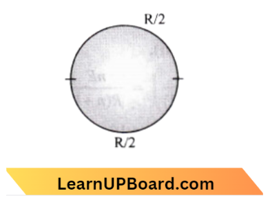
∴ \(R^{\prime} =\frac{R}{4}\)
Question 53. Five equal resistance each of resistance R are connected as shown in the figure. A battery of V volts is connected between A and B. The current flowing in AFCEF will be:
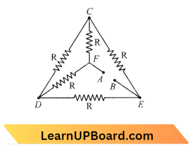
- \(\frac{3 V}{R}\)
- \(\frac{V}{R}\)
- \(\frac{V}{2 R}\)
- \(\frac{2 V}{R}\)
Answer: 3. \(\frac{V}{2 R}\)
Given circuit can be reduced to,
Required current, I=\(\frac{V}{2 R}\)
Question 54. Two 220-volt, 100-watt bulbs are connected first in series and then in parallel. Each time combination is connected to a 220-volt a.c. supply line. The power drawn by the combination in each case respectively will be:
- 50 watt, 10 watt
- 100 watt, 50 watt
- 200 watt, 150 watt
- 50 watt, 200 watt
Answer: 4. 50 watt, 200 watt
R=\(\frac{V^2}{P}=\frac{220 \times 220}{100}=484 \Omega\)
In series, \(\mathrm{R}_{e q} =484+484=968 \Omega\)
∴ \(\mathrm{R}_{e q} =\frac{\mathrm{V}^2}{968}=\frac{220 \times 220}{968}=200 \Omega\)
NEET Physics Mcqs Current Electricity
Question 55. The current (1) in the given circuit is:
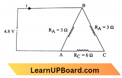
- 1.6 A
- 2 A
- 0.32 A
- 3.2 A
Answer: 2. 2 A
Since, the resistances \(R_{\mathrm{B}}\) and \(R_{\mathrm{C}}\) are connected in series in the given circuit, then their effective resistance will be the same.
⇒ \(R^{\prime} =R_{\mathrm{B}}+R_{\mathrm{C}}\)
=6+6=12 \(\Omega\)
Now, \(R_A\) and \(R^{\prime}\) are in parallel order, hence, the net resistance of the circuit will be,
R=\(\frac{R^{\prime} \times R_{\mathrm{A}}}{R^{\prime}+R_{\mathrm{A}}}=\frac{12 \times 3}{12+3}=\frac{36}{15} \Omega\)
Now, the current flow in the circuit,
i=\(\frac{V}{R}=4.8 \times \frac{15}{36}=2 \mathrm{~A}\)
Question 56. A heating coil is labeled 100 W, 220 V. The coil is cut into two halves and the two pieces are joined in paraded to the same source. The energy now liberated per second is:
- 25 J
- 50 J
- 200 J
- 400 J
Answer: 4. 400 J
When a heating coil is cut into two halves and then joined in parallel, the coil’s resistance is decreased to one-fourth of its prior value.
As, \(\left(H \alpha \frac{1}{R}\right)\), for constant voltage, the energy liberated per second becomes 4 times, i.e.
4 \(\times 100=400 \mathrm{~J}\)
Question 57. Three resistances each of 4\(\Omega\) are connected to form a triangle. The resistance between any two terminals is:
- 12 \(\Omega\)
- \(\frac{2}{1} \Omega\)
- 6 \(\Omega\)
- \(\frac{8}{3} \Omega\)
Answer: 4. \(\frac{8}{3} \Omega\)
Here, the two resistances are connected in series and the resultant is connected in parallel with the third resistance.
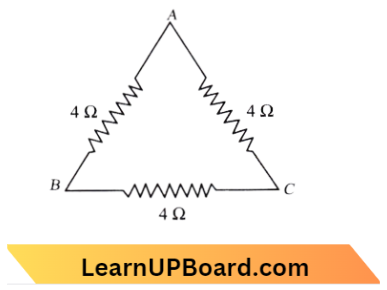
Therefore, equivalent resistance will be, \(\frac{1}{\mathrm{R}_{\mathrm{BC}}}=\frac{1}{4}+\frac{1}{8}\)
⇒ \(\frac{1}{\mathrm{R}_{\mathrm{BC}}}=\frac{2+1}{8}\)
∴ \(R_{B C}=\frac{8}{3} \Omega\)
NEET Physics Mcqs Current Electricity
Question 58. Six similar bulbs are connected as shown in the figure with a DC source of emf E and zero internal resistance. The ratio of power consumption by the bulbs when (1) all are glowing and (2) in the situation when two from section A and one from section B are glowing will be:
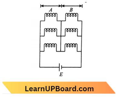
- 9: 4
- 1: 2
- 2: 1
- 4: 9
Answer: 1. 9: 4
1. When all bulbs are glowing then,
Here, \(R_{e q}=\frac{R}{3}+\frac{R}{3}=\frac{2 R}{3}\)
Power, \(P_i=\frac{E^2}{R_{\text {eq }}}+\frac{3 E^2}{2 R}\)
(2) Two from section A and one from section B are glowing,
Then \(R_{e q}=\frac{R}{2}+R=\frac{3 R}{2}\)
Power, \(P_f=\frac{2 E^2}{3 R}\)
From (1) and (2),
∴ \(\frac{P_i}{P_f}=\frac{3 E^2 3 R}{2 R \cdot 2 E^2}\)=9: 4
Question 59. The internal resistance of 2.1 V cell which gives a current of 0.2 A through a resistance of 10\(\Omega\) is:
- 0.2\(\Omega\)
- 0.5\(\Omega\)
- 0.8\(\Omega\)
- 1.0\(\Omega\)
Answer: 2. 0.5\(\Omega\)
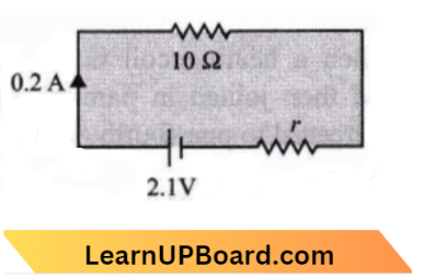
⇒ \(\mathrm{I} =\frac{E}{r+R}\)
0.2 =\(\frac{2.1}{r+10}\)
r =0.5 \(\Omega\)
Question 60. A cell having an EMF 8 and internal resistance r is connected across a variable external resistance R. As the resistance R is increased, the plot of potential difference V across R is given by:
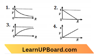
Answer: 3.
E=\(I(R+r)=I R+I r\)
and E=\(V+I r \)
E=\(V+\frac{E n}{R+r}\)
V=\(E-\frac{E n}{R+r} \times r\)
NEET Physics Mcqs Current Electricity
Question 61. A student measures the terminal potential difference (V) of a cell of (of emf e and internal resistance r) as a function of the current (l) flowing through it. The slope and intercept of the graph between V and l, then respectively, equal:
- e and – r
- – r and e
- r and – e
- – e and r
Answer: 2. – r and e
Using ohm’s law, \(\frac{d V}{d \mathrm{I}}\) =-r
and V = E,
if I =0
slope of graph =-r
And Intercept=E
Question 62. For a cell, a terminal potential difference is 2.2 V when the circuit is open. If it reduces to 1.8 V when the cell is connected to a resistance of 5\(\Omega\). The internal resistance of cell (r) is then
- \(\frac{10}{9} \Omega\)
- \(\frac{9}{10} \Omega\)
- \(\frac{11}{9} \Omega\)
- \(\frac{5}{9} \Omega\)
Answer: 1. \(\frac{10}{9} \Omega\)
The terminal potential difference, V=E-I r
V=\(E-\left[\frac{E}{R-r}\right] r=\frac{E R}{R+r}\)
From given condition =E=2.2 and where R=5
then potential, V=1.8 \(\mathrm{~V}\)
Therefore, 1.8=\(\frac{2.2 \times 5}{5+r}\)
= \(\frac{10}{9} \Omega\)
Question 63. A set of ‘n equal resistors, of value ‘R’ each, are connected in series to a battery of emf ‘E and internal resistance The current drawn is I. Now, the ‘n resistors are connected in parallel to the same battery. Then, the current drawn from the battery becomes 10I. The value of ‘n is :
- 20
- 11
- 10
- 9
Answer: 3. 10
Given
A set of ‘n equal resistors, of value ‘R’ each, are connected in series to a battery of emf ‘E and internal resistance The current drawn is I. Now, the ‘n resistors are connected in parallel to the same battery. Then, the current drawn from the battery becomes 10I.
According to the question,
When n equal resistors of resistance R connected in series then Current, I=\(\frac{E}{n R+r}\) → Equation 1
Where, r= internal resistance of the battery
nr= equivalent resistance of n resistors in series
In question,r=R
I=\(\frac{E}{R(n+1)}\) → Equation 2
Similarly when n equal resistors of resistance R are connected in parallel then,
Current, \(I^{\prime}=\frac{E}{\frac{R}{n}+R}\)
Where, \(\frac{R}{n}={ }^n\) equivalent resistance of n resistors in parallel
It is given that, \(\Gamma\)=10 I
10 I=\(\frac{E}{\frac{R}{n}+R}=\frac{n E}{(n+1) R}\) Equation 2
From (1) and (2),
10\(\left(\frac{E}{R(n+1)}\right) =\frac{n E}{R(n+1)}\)
n =10
10 I=\(\frac{R}{\frac{R}{n}+R}\)
Divide (2) by (1)
10 =\(\frac{(n+1) R}{\left(\frac{1}{n}+1\right) R}\)
n =10
Question 64. A battery consists of a variable number ‘n of identical cells (having internal resistance V each) which are connected in series. The terminals of the battery are short-circuited and the current I is measured. Which of the graphs shows the correct relationship between I and n?
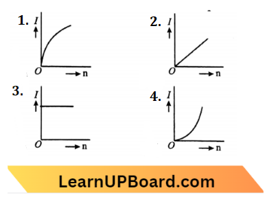
Answer: 3.
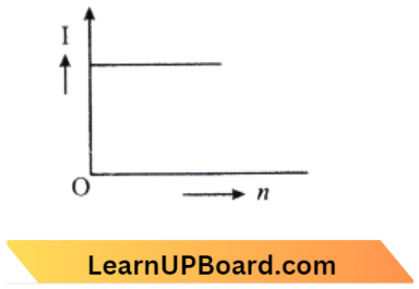
Since, I=\(\frac{n E}{n r}=\frac{E}{r}\)
So, I am independent of n and i is constant.
NEET Physics Mcqs Current Electricity
Question 65. Two cells, having the same e.m.f. are connected in series through an external resistance R. Cells have internal resistances \(r_1\) and \(r_2\left(r_1>r_2\right)\) respectively. When the circuit is closed, the potential difference across the first cell is zero. The value of l is:
- \(r_1+r_2\)
- \(r_1-r_2\)
- \(\frac{r_1+r_2}{2}\)
- \(\frac{r_1-r_2}{2}\)
Answer: 2. \(r_1-r_2\)
According to the question, \(E-I r_1=0 and \mathrm{I} =\frac{E+E}{r_1+r_2+R} \)
\(\frac{E}{r_1} =\frac{2 E}{r_1+r_2+R} \) \(r_1+r_2+R =2 r_1-r_2\)R =\(r_1-r_2\)
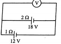
Question 66. Two batteries, one of EMF 18 volts and internal resistance 2 Ω and the other of EMF 12 volts and internal resistance 1 Ω, are connected as shown. The voltmeter V will record a reading of:
- 30 volt
- 18 volt
- 15 volt
- 14 volt
Answer: 4. 14 volt
Reading of voltmeter =\(\frac{\frac{E_1}{r_1}+\frac{E_2}{r_2}}{\frac{1}{r_1}+\frac{1}{r_2}}=\frac{E_1 r_2+E_2 r_1}{r_1+r_2}\)
Putting value we get 14 volts.
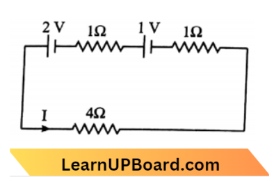
Question 67. For the circuit shown in the figure, the current I will be:
- 0.75 A
- 1 A
- 1.5 A
- 0.5 A
Answer: 2. 1 A
By \(\mathrm{KVL}\) in a closed loop \(\mathrm{ABCDA}\),
⇒ \(V_{\mathrm{A}}-I \times 4-I \times 1+4-I \times 1+2 =V_{\mathrm{A}} \)
⇒ \(-6 \mathrm{I}+6\) =0
I =1 \(\mathrm{~A}\)
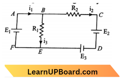
Question 68. For the circuit given below, the Kirchhoffs loop rule for the loop BCDEB is given by the equation:
- \(-\mathrm{i}_2 \mathrm{R}_2+\mathrm{E}_2-\mathrm{E}_3+\mathrm{i}_3 \mathrm{R}_1\)=0
- \(\mathrm{i}_2 \mathrm{R}_2+\mathrm{E}_2-\mathrm{E}_3-\mathrm{i}_3 \mathrm{R}_1\)=0
- \(\mathrm{i}_2 \mathrm{R}_2+\mathrm{E}_2-\mathrm{E}_3+\mathrm{i}_3 \mathrm{R}_1\)=0
- –\(\mathrm{i}_2 \mathrm{R}_2+\mathrm{E}_2+\mathrm{E}_3+\mathrm{i}_3 \mathrm{R}_1\)=0
Answer: 2. \(\mathrm{i}_2 \mathrm{R}_2+\mathrm{E}_2-\mathrm{E}_3-\mathrm{i}_3 \mathrm{R}_1\)=0
The circuit diagram is given by,
Applying the KVL rule to Loop BCDEB.
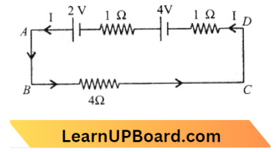
Question 69. The potential difference \(\left(V_A-V_B\right)\) between the points A and B in the given figure is:
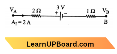
- – 3 V
- + 3 V
- + 6 V
- + 9 V
Answer: + 9 V
Applying Kirchoff’s law
⇒ \(\mathrm{V}_{\mathrm{B}} =\mathrm{V}_{\mathrm{A}}-(2 \times 2)-3-3(2 \times 1)\)
∴ \(\mathrm{V}_{\mathrm{A}}-\mathrm{V}_{\mathrm{A}} =9 \mathrm{~V}\)
Current Electricity MCQs For NEET
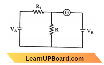
Question 70. In the circuit shown cells A and B have negligible resistances. For VA =12 V, R1= 500 Ω, and R = 100 Ω the galvanometer (G) shows no deflection. The value of VB is:
- 4 V
- 2V
- 12 V
- 6V
Answer: 2. 2V
The situation is shown in the given figure. then we use Kirchhofl’s law
500 I+100 I =12
I =\(\frac{12 \times 10^{-2}}{6}=2 \times 10^{-2} \mathrm{~A} \)
∴ \(V_B =100\left(2 \times 10^{-2}\right)=2 \mathrm{~V}\)
Question 71. In the circuit shown in the figure, if the potential at point A is taken to be zero, the potential at point B is:
- – 1 V
- + 2 V
- -2 V
- + 1 V
Answer: 4. + 1 V
Using kirchhoff’s law in loop A C D B
⇒ \(V_A+1+(1)(2)-2 =V_B\)
0+1 =\(V_B\)
∴ \(V_B \)=1 volt
Question 72. Consider the following two statements;
(1) Kirchhoff’s junction law follows from the conservation of charge
(2) Kirchhoff’s loop law follows from the conservation of energy.
Which of the following is correct?
- Both (1) and (2) are wrong.
- (1) is correct and (2) is wrong.
- (1) is wrong and (2) is correct.
- Both (1) and (2) are correct.
Answer: 4. Both (1) and (2) are correct.
Kirchhoff’s second law follows from the conservation of energy.
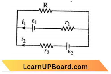
Question 73. See the electrical circuit shown in the figure which of the following equations is a correct equation for it?
- \(e_1-\left(i_1+i_2\right) R-i_1 r_1\)=0
- \(e_2-i_1 r_2-e_1-i_1 r_1\)=0
- \(-e_2-\left(i_1+i_2\right) R+i_2 r_2\)=0
- \(e_1-\left(i_1+i_2\right) R+i_1 r_1\)=0
Answer: 1. \(e_1-\left(i_1+i_2\right) R-i_1 r_1\)=0
Applying Kirchhoff’s law, \(\Sigma \)V=0
Here \(\epsilon_1-\left(i_1+i_2\right) R-i_1 r_1\)=0
Question 74. KirchhofFs first and second laws of electrical circuits are consequences of:
- conservation of energy and electric charge respectively
- conservation of energy
- conservation of electric charge and energy respectively
- conservation of electric charge
Answer: 3. conservation of electric charge and energy respectively
Kirchhoffs first and second laws of electrical circuits are consequences of the conservation of energy.
Current Electricity MCQs For NEET
Question 75. Kirchhoff’s first law of electricity follows:
- the only law of conservation of energy
- the only law of conservation of charge
- law of conservation of both energy and charge
- sometimes law of conservation of energy and some other times law of conservation of charge
Answer: 2. only the law of conservation of charge
Kirchhoff’s first law applies to currents at a junction in a circuit. It states that at a junction in an electrical circuit, the sum of currents flowing into the junction is equal to the sum of currents flowing out of the junction. Kirchhoff’s first law is in favor of the law of charge conservation. This is because a point in a circuit cannot be both a source as well as a sink of charge.
Question 76. The resistance of the four. RMS P, Q, R, and S in a Wheatstone’s bridge are 10 Ω. 30 Ω, 30 Ω, and 90 Ω, respectively. The emf and internal resistance of the cell are 7 V and 5 Ω respectively. If the galvanometer resistance is 50Ω, the current drawn from the cell will be:
- 1.0 A
- 0.2 A
- 0.1A
- 2.0 A
Answer: 2. 0.2 A
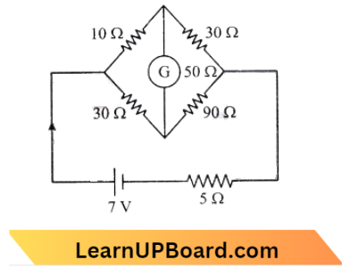
Total resistance of Wheatstone Bridge,
=\(\frac{(40)(120)}{40+120}=30 \Omega\)
Current through the coil,
= \(\frac{7 \mathrm{~V}}{(5+30) \Omega}=\frac{1}{5} \mathrm{~A}\)
= 0.2 \(\mathrm{~A}\)
Question 77. Three resistances P, Q, and R each of 2 Ω, and an unknown resistance S form the four arms of a Wheatstone bridge circuit. When a resistance of 6Ω is connected in parallel to S the bridge gets balanced. What is the value of S’?
- 3 Ω
- 6 Ω
- 1 Ω
- 2 Ω
Answer: 1. 3 Ω
Let X be the equivalent resistance between S and 6 \(\Omega\)
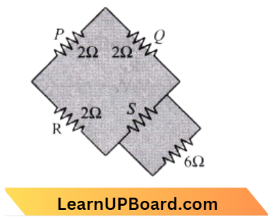
The equivalent circuit is,
Now for the balanced Wheatstone bridge, we have
⇒ \(\frac{R}{X}=\frac{R}{X}=\frac{1}{2}\)
X=2 \(\Omega\)
Now for the balanced Wheatstone bridge, we have
⇒ \(\frac{R}{X}=\frac{R}{X}=\frac{1}{2}\)
X=2 \(\Omega\)
from equation (1) we have
⇒ \(\frac{1}{2}=\frac{1}{S}+\frac{1}{6}\)
⇒ \(\frac{1}{S}=\frac{1}{2}-\frac{1}{6}=\frac{2}{6}\)
S=3 \(\Omega\)
Current Electricity MCQs For NEET
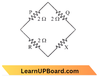
Question 78. In the circuit shown, if a conducting wire is connected between points A and B, the current in this wire will:
- flow from B to A
- flow from A to B
- flow in the direction which will be decided by the value of V
- be zero.
Answer: 1. flow from B to A
According to the diagram,
⇒ \(V_A-V_B =\left[V-\left(\frac{V}{8} \times 4\right)\right]-\left[V-\left(\frac{V}{4} \times 1\right)\right]\)
=\(-\frac{V}{2}+\frac{V}{4}=-\frac{V}{4}\)
∴ \(V_B >V_A\) .
Question 79. For the network shown in the figure the value of the current i is:
- \(\frac{9 \mathrm{~V}}{35}\)
- \(\frac{18 \mathrm{~V}}{5}\)
- \(\frac{5 \mathrm{~V}}{9}\)
- \(\frac{5 \mathrm{~V}}{18}\)
Answer: 4. \(\frac{5 \mathrm{~V}}{18}\)
Since the network is balanced, it is Wheatstone’s bridge. Therefore, no current flows through the arm AC,
Here \( R_1\) and \(R_2\) are in series,
⇒ \(R_1{ }^{\prime}=R_1+R_2=4+2=6 \Omega\)
⇒ \(R_3\) and \(R_4\) are in series
⇒ \(R^{\prime \prime}=R_3+R_4=6+3=9 \Omega\)
Now \(R^{\prime} and R^{\prime \prime}\) are in parallel,
⇒ \({1}{R_{e q}} =\frac{1}{R^{\prime}}+\frac{1}{R^{\prime \prime}}\)
= \(\frac{1}{6}+\frac{1}{9}=\frac{5}{18}\)
⇒ \(R_{e q} =\frac{16}{5}\)
Now from V =\(I R_{e q}\)
I = \(\frac{V}{R_{e q}}=\frac{5}{18} \mathrm{~V}\)
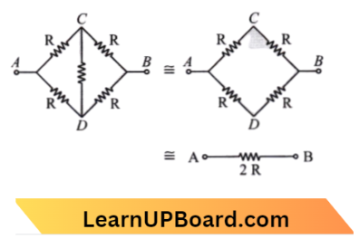
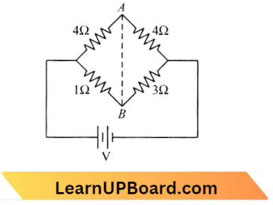
Question 80. In a Wheatstone’s bridge, all four arms have equal resistance R. If the resistance of the galvanometer arm is also R, the equivalent resistance of the combination as seen by the battery is:
- \(\frac{R}{4}\)
- \(\frac{R}{2}\)
- R
- 2 R
Answer: 3. R
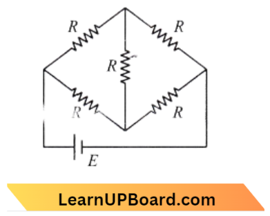
Resistance seen by the battery = Equivalent resistance between A and B is R.
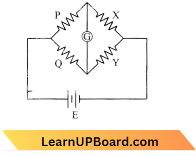
Question 81. A Wheatstone bridge is used to determine the value of unknown resistance X by adjusting the variable resistance Y as shown in the figure. For the most precise measurement of X, the resistances P and Q.
- should be approximately equal to 2X
- should be approximately equal and small
- should be very large and unequal
- do not play any significant role
Answer: 2. should be approximately equal and are small
For a balanced Wheatstone bridge, the current through a galvanometer is zero.\(\frac{P}{Q}=\frac{X}{Y}\)
So, resistance P and Q should be approximately equal and small.
Question 82. A resistance wire connected in the left gap of the meter bridge balances a 10 Ω resistance in the right gap at a point that divides the bridge wire in the ratio 3: 2. If the length of the resistance wire is 1.5 m, then the length of 1Ω of the resistance wire is :
- 1.0 x 10⁻¹ m
- 1.5 x 10⁻¹ m
- 1.5 x 10⁻² m
- 1.0 x 10⁻² m
Answer: 1. 1.0 x 10⁻¹ m
The meter bridge is,
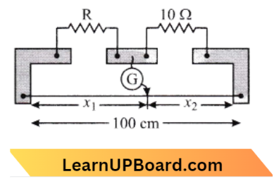
Ratio of bridge wire, \(\frac{x_1}{x_2}=\frac{3}{2}\) → Equation 1
For balance condition of meter bridge, \(\frac{R}{10}=\frac{x_1}{x_2}\) → Equation 2
From eq. (1) and (2),
⇒ \(\frac{R}{10} =\frac{3}{2}\)
⇒ \(\mathrm{R} =\frac{3}{2} \times 10=15 \Omega\)
So the length of wire whose resistance is 10 \Omega is 1.5 \(\mathrm{~m}\).
Length of 1 \(\Omega\) resistance is,\(\frac{1.5}{15}=0.1=1 \times 10^{-1} \mathrm{~m}\) .
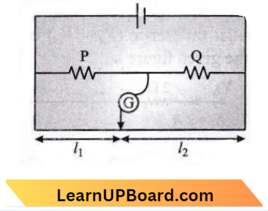
Question 83. The meter bridge is shown in the balance position with \(\frac{\mathrm{P}}{\mathrm{Q}}=\frac{l_1}{l_2}\). If we now interchange the positions of the galvanometer and cell, will the bridge work? If yes, that will be balanced conduction?
- \(yes \frac{\mathrm{P}}{\mathrm{Q}}=\frac{l_2-l_1}{l_2+l_1}\)
- don’t all no null point
- yes \(\frac{\mathrm{P}}{\mathrm{Q}}=\frac{l_2}{l_1}\)
- yes,\(\frac{\mathrm{P}}{\mathrm{Q}}=\frac{l_1}{l_2}\)
Answer: 4. yes,\(\frac{\mathrm{P}}{\mathrm{Q}}=\frac{l_1}{l_2}\)
The meter bridge is based on a balanced Wheatstone bridge.
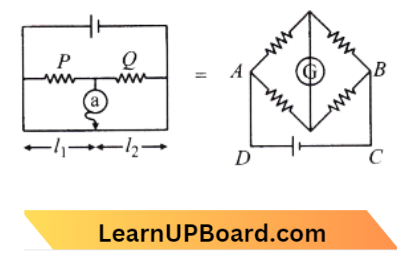
If we interchange the position of the Galvanometer and cell then there is no effect because is in balance Condition, So \(\frac{P}{Q}=\frac{l_1}{l_2}\)
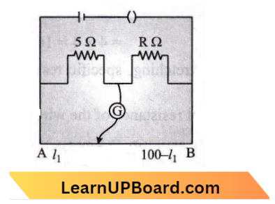
Question 84. The resistance in the two arms of the meter bridge is 5 \(\Omega\) and R \(\Omega\), respectively. When the resistance R is shunted with an equal resistance the new balance point is at 1.6 l1. The resistance R is:
- 10 \(\Omega\)
- 15 \(\Omega\)
- 20 \(\Omega\)
- 25 \(\Omega\)
Answer: 2. 15 \(\Omega\)
In the First case,
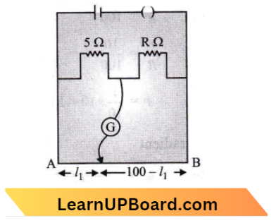
At balance point,\(\frac{5}{R}=\frac{l_1}{100-l_1}\) → Equation 1
In the second case,
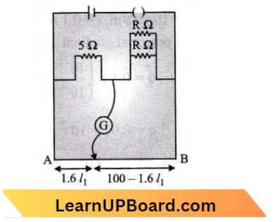
At balance point,\(\frac{5}{\left(\frac{R}{2}\right)}=\frac{1.6 l_1}{100-1.6 l_1}\) → Equation 2
Divide eq. (1) by eq (2), We get,
⇒ \(\frac{1}{2} =\frac{100-1.6 l_1}{1.6\left(100-l_1\right)}\)
⇒ \(160-1.6 l_1 =200-3.2 l_1\)
⇒ \(1.6 l_1 =40 or l_1=\frac{40}{1.6}=25 \mathrm{~cm}\)
Substituting this value in eq (1), we get,
⇒ \(\frac{5}{R} =\frac{25}{75}\)
∴ \(\mathrm{R} =\frac{375}{25} \Omega=15 \Omega\) .
Question 85. In a potentiometer circuit, a cell of EMF 1.5 V gives a balance point at 36 cm length of wire. If another cell of EMF 2.5 V replaces the first cell, then at what length of the wire, the balance point occur?
- 60 cm
- 21.6 cm
- 64 cm
- 62 cm
Answer: 1. 60 cm
Given, \(\varepsilon_1=1.5 \mathrm{~V}\)
Balance length,
We know, \(l_1 =36 \mathrm{~cm}\)
⇒ \(\varepsilon_2 =2.5 \mathrm{~V}\)
⇒ \(l_2 =?\)
⇒ \(\frac{\varepsilon_1}{\varepsilon_2}=\frac{l_1}{l_2}\)
⇒ \(l_2=\frac{\varepsilon_2 l_1}{\varepsilon_1}=\frac{2.5 \times 36}{1.5}\)
⇒ \(l_2=36 \times \frac{5}{3}\)
∴ \(l_2=60 \mathrm{~cm}\)
Question 86. A potentiometer is an accurate and versatile device to make electrical measurements of EMF because the method involves:
- cells
- potential gradients
- a condition of no current flow through the galvanometer
- a combination of cells, galvanometer, and resistance
Answer: 3. a condition of no current flow through the galvanometer
Reading of potentiometers is accurate because while taking reading it does not draw any current from the circuit.
Question 87. A potentiometer wire is 100 cm long and a constant potential difference is maintained across it. Two cells are connected in series in opposite directions. The balance points are obtained at 50 cm and 10 cm from the positive end of the wire in the two cases. The ratio of emf is:
- 5: 4
- 3: 4
- 3: 2
- 5: 1
Answer: 3. 3: 2
Given
A potentiometer wire is 100 cm long and a constant potential difference is maintained across it. Two cells are connected in series in opposite directions. The balance points are obtained at 50 cm and 10 cm from the positive end of the wire in the two cases.
The emf of the cell is directly proportional to the balancing length, \(E \propto l\)
In the question, two cases are given. In the first case cells are connected in series, \(\varepsilon_1=E_1+E_2\)=50 → Equation 1
In \(II ^{\text {nd }}\) case cells are connected in series but in opposite direction
⇒ \(\varepsilon_2=E_1-E_2\)=10 → Equation 2
From eq. (1) \(\div \)(2)
we get,\(\frac{E_1+E_2}{E_1-E_2} =\frac{50}{10}\)
⇒ \(\frac{E_1}{E_2} =\frac{5+1}{5-1} \)
= \(\frac{6}{4}=\frac{3}{2}\)=3: 2
Question 88. A potentiometer wire has a length of 4 m and resistance of 8 \(\Omega\). The resistance that must be connected in series with the wire and an accumulator of emf 2 V, so as they get a potential gradient of 1 m V per cm on the wire is:
- 32 \(\Omega\)
- 40 \(\Omega\)
- 44 \(\Omega\)
- 48 \(\Omega\)
Answer: 1. 32 \(\Omega\)
Given resistance of potentiometer, R=8 \(\Omega\) emf of accumulator, E=2 \(\mathrm{~V}\)
Potential gradient, \(\frac{d v}{d r}=1 \mathrm{mV} / \mathrm{cm}\)
Potential due to wire of length, =1 \times 400
= \(400 \mathrm{mV}=0.4 \mathrm{~V}\)
Let a resistor \(R_s\) is connected in series, then
⇒ \(\Delta V =\frac{V}{R+R_5} \times R\)
0.4 =\(\frac{2}{8+R} \times 8\)
8+R =\(\frac{16}{0.4}\)=40
40-8 =32 \(\Omega\)
Question 89. A potentiometer wire of length L and a resistance r are connected in series with a battery of e.m.f. E0 and a resistance r1. An unknown e.m.f. E is balanced at a length l of the potentiometer wire. The e.m.f E will be given by:
- \(\frac{L E_0 r}{l r_1}\)
- \(\frac{E_0 r}{\left(r+r_1\right)} \cdot \frac{l}{L}\)
- \(\frac{E_0 l}{L}\)
- \(\frac{L E_0 r}{\left(r+r_1\right) l}\)
Answer: 2. \(\frac{E_0 r}{\left(r+r_1\right)} \cdot \frac{l}{L}\)
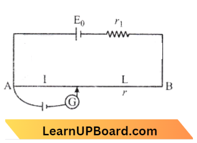
Current in potentiometer wire is, I=\(\frac{E_0}{r+r_1}\)
The voltage drop across potentiometer wires,
⇒ \(V_0=\frac{E_0 r}{r+r_1}\)
So, E=\(K I=\frac{V_0 I}{L}\)
E=\(\frac{E_0 r l}{\left(r+r_1\right) L}\)
Question 90. A potentiometer circuit has been set up for finding the internal resistance of a given cell. The main battery, used across the potentiometer wire, has an EMF of 2.0 V and a negligible internal resistance. The potentiometer wire itself is 4 m long. When the resistance R, connected across the given cell, has a value of (1) infinity (2) 9.5 Ω The ‘balancing lengths’, on the potentiometer wire are found to be 3 m and 2.85 m, respectively. The value of the internal resistance of the cell is:
- 0.25 Ω
- 0.95Ω
- 0.5 Ω
- 0.75 Ω
Answer: 3. 0.5 Ω
According to the question, emf , \(\epsilon=2 \mathrm{~V}\)
and Potentiometer wire length, l=4 \(\mathrm{~m}\)
Potential drop per unit length is :
⇒ \(\phi=\frac{\epsilon}{l}=\frac{2}{4}=0.5 \mathrm{~V} / \mathrm{m}\)
In \(1^{\text {st }} case, \epsilon=\phi l_1\) → Equation 1
In \(2^{\text {nd }} case, \quad V=\phi l_2\) → Equation 2
From eq. (1) and (2)
⇒ \(\frac{\epsilon}{V}=\frac{l_1}{l_2}\)
Now for \(2^{\text {nd }}\) case
and \(\epsilon^{\prime} =l(r+R)\)
V =I R
r =\(R\left(\frac{l_1}{l_2}-1\right)=9.5\left(\frac{3}{2.85}-1\right)\)
= \(\frac{0.15}{2.85} \times 9.5 \Omega=0.5 \Omega\)
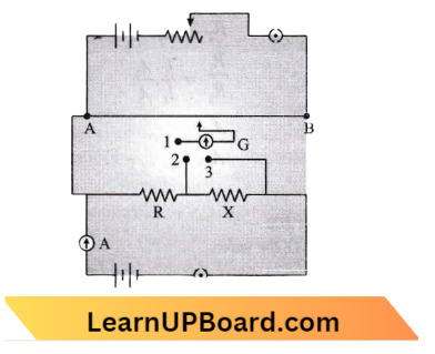
Question 91. A potentiometer circuit is set up as shown. The potential gradient across the potentiometer wire is k volt/cm, and the ammeter, present in the circuit, reads 1.0 A when the two-way key is switched off. The balance points when the key between the terminals (1) 1 and 2 (2) 1 and 3, is plugged in, are found to be at lengths f cm l2 cm respectively, the magnitude of the resistors R and X, in ohm, are then, equal respectively, to:
- \(\mathrm{k}\left(\mathrm{l}_2-\mathrm{l}_1\right)\) and \(\mathrm{kl}_2\)
- \(\mathrm{kl}_2 \)and \(\mathrm{k}\left(\mathrm{l}_2-\mathrm{l}_1\right)\)
- \(\mathrm{k}\left(\mathrm{l}_2-\mathrm{l}_1\right)\) and \(\mathrm{kl}_1\)
- \(\mathrm{kl}_1\) and \(\mathrm{kl}_2\)
Answer: 2. \(\mathrm{kl}_2 \)and \(\mathrm{k}\left(\mathrm{l}_2-\mathrm{l}_1\right)\)
Let the balancing length for R be \(l_1\) and balancing length for (R+X) is \(l_2\)
Then, i R=k \(l_1\)
and i(R+X)=\(k l_2\)
It is given that, i=1 \(\mathrm{~A}\)
R=k \(l_1 \) → Equation 1
R+X=k\( l_2\) → Equation 2
From (1) and (2)
X=k\(\left(l_2-l_1\right)\)
Question 92. A cell can be balanced against 110 cm and 100 cm of potentiometer wire, respectively with and without being short-circuited through a resistance of 10Ω. Its internal resistance is:
- 1.0 Ω
- 0.5 Ω
- 2.0 Ω
- zero
Answer: 1. 1.0 Ω
In a potentiometer experiment when we find the internal resistance of a cell. Let E be the emf of the cell and V the potential difference.
Then, \(\frac{E}{V}=\frac{l_1}{l_2}\) [\(l_1\). and \(l_2\) are length of wire]
Since, \(\frac{E}{V}=\frac{R+r}{R}[E=I(R+r) an V=1 R]\)
⇒ \(\frac{R+r}{R} =\frac{l_1}{l_2} 1+\frac{r}{R} =\frac{110}{100}\)
⇒ \(\frac{r}{R}=\frac{10}{100}\)
r=\(\frac{1}{10} \times 10=1 \Omega\)
Question 93. The resistivity of the potentiometer wire is 10-7 Ω-m and its area of cross-section is 10-6m2. When a current i = 0.1 A flows through the wire, its potential gradient is:
- 10-2V/m
- 10-4 V/m
- 0.1-2 V/m
- 10-2V/m
Answer: 1. 10-2V/m
(A) Potential gradient
= Potential fall per unit length =\(\frac{V}{l}\)
= current \(\times\) resistance per unit length
=i \(\times \frac{R}{l}\) .
but, \(\mathrm{R}=\frac{\rho I}{A}\)
\(\frac{R}{I}=\frac{\rho}{A}\)Potential gradient =i \(\times \frac{\rho}{A}\)
Given, \(\rho=10^{-7} \Omega-\mathrm{m}, i=0.1 \mathrm{~A} and \mathrm{A}=10^{-6} \mathrm{~m}^2\)
Therefore, potential gradient \(\phi=0.1 \times\left(\frac{10^{-7}}{10^{-6}}\right)=0.1 \times \frac{1}{10}\)
∴ \(\phi=0.01=10^{-2} \frac{\mathrm{V}}{\mathrm{m}}\)
Question 94. A potentiometer measures the potential difference more accurately than a voltmeter, because:
- it has a wire of high-resistance
- it has a wire of low resistance
- it does not draw current from the external circuit
- it draws a heavy current from the external circuit
Answer: 3. it does not draw current from the external circuit
When we use a potentiometer to measure the emf of a cell, no current is pulled from the external circuit. As a result, the actual value of a cell is found in this condition. In this way, a potentiometer is equivalent to an infinite-resistance ideal voltmeter
Question 95. A potentiometer consists of a wire of length 4 m and resistance 10 \(/omega\). It is connected to a cell of emf 2 V. The potential gradient of the wire is
- 0.5 V/m
- 2 V/m
- 5 V/m
- 10 V/m
Answer: 1. 0.5 V/m
We have, Potential gradient }=\(\frac{\text { Potential applied }}{\text { Length of wire }}\)
⇒ \(\phi=\frac{V}{I}\)
Given, V=2 \(\mathrm{~V}, l=4 \mathrm{~m}\)
∴ \(\phi=\frac{2}{4}=0.5 \mathrm{~V} / \mathrm{m}\)